In the realm of electronics, the 7-segment display emerges as an invaluable component for visualizing numerical data. This ubiquitous device is commonly found in digital clocks, calculators, and countless other electronic systems. Among its many configurations, the common cathode variant stands out for its straightforward yet effective design. In this comprehensive guide, readers can expect to delve into the intricacies of the common cathode 7-segment display pin configuration, discover its applications, and gain insights into its operational principles. With this understanding, enthusiasts and professionals alike can harness its potential in their projects.
The common cathode 7-segment display comprises seven individual segments, each illuminated to represent numerals from 0 to 9. In this setup, all the cathodes of the segments are interconnected, leading to a common ground. When analyzing the pin configuration of a common cathode display, one will observe that it typically comprises a set of pins corresponding to each segment as well as additional pins serving as the common cathode connections.
To elucidate this configuration further, let’s break down the pin layout. A standard 7-segment display will exhibit the following primary pins:
- Segment A: Positioned usually at the top center, illuminating this segment forms the top of the digit.
- Segment B: Located at the top right, segment B complements the numeral by depicting the upper right part.
- Segment C: Found at the bottom right, this segment completes the shape of the numbers.
- Segment D: Positioned at the bottom, segment D forms the base of the digits.
- Segment E: Located at the bottom left, it provides the necessary contrast for specific numeral representations.
- Segment F: Found at the upper left, segment F works in conjunction with others to display the required figures.
- Segment G: At the center, segment G serves to create the horizontal bar that connects the vertical segments.
- Common Cathode Pin: This pin connects to the ground, completing the circuit when segments are activated.
The beauty of the common cathode display lies in its operational mechanism. Segment illumination is achieved by supplying a positive voltage to the corresponding segment’s pin. When this voltage is applied, the current flows from the regulated positive source through the segment and into the common cathode, thus resulting in the illumination of that specific segment. Notably, this configuration allows multiple segments to be lit simultaneously, enabling the display of a range of digits from 0 to 9, including some alphanumeric characters.
When it comes to applications, the 7-segment common cathode display is ubiquitous. In electronic devices like digital clocks, each digit corresponds to a different segment that can be turned on or off based on the time value. The auditory alarms, timers, and even scores in a competition rely on intact 7-segment displays to ensure visibility. Furthermore, one can find their essence in calculators, where they exhibit numeric inputs dynamically.
Integration with microcontrollers has further enhanced the utility of the common cathode display. Arduino, Raspberry Pi, and other microcontrollers can be programmed to communicate with these displays. By controlling which segments receive power, one can easily create compelling visual outputs. For instance, a common microcontroller might generate a command to light up segments A, B, and C to display the number ‘3’. With a proper understanding of the pin configuration and circuitry, creative applications abound—from alarm systems to rudimentary games.
A critical aspect for users to consider is the required resistor. In most applications, especially those interfacing with microcontrollers, a current-limiting resistor is indispensable. This component safeguards the display from excessive current, which could lead to burnout. Calculation of the appropriate resistor value can be efficiently achieved using Ohm’s Law, where users should account for the supply voltage, the forward voltage drop across the individual segments, and the desired current flowing through them.
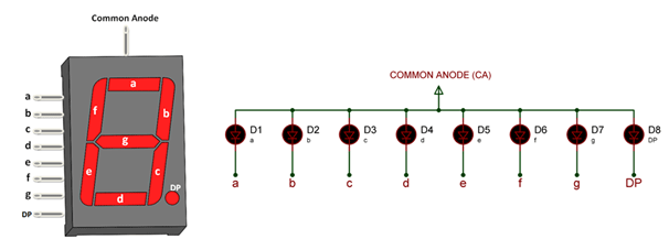
Moreover, there are several variations of 7-segment displays, including the common anode type. While the common cathode display allows segments to be activated by applying a positive voltage, the common anode display functions inversely—requiring a low voltage to illuminate segments. Knowing the difference between these two configurations is paramount when opting for specific applications, as they significantly influence the circuit design and required logic levels.
In summary, the common cathode 7-segment display serves as a vital instrument in the digital presentation of numeric data across a multitude of electronic devices. Understanding its pin configuration, the functionality of its segments, and the appropriate methodologies for integrating it into electronic systems can render designers and hobbyists adept in their respective pursuits. As digital interfaces continue to evolve in complexity and capability, the quintessential 7-segment display remains a steadfast companion in conveying essential information succinctly and effectively.