Have you ever pondered how those elegant, single-digit displays illuminate our devices with simplicity and clarity? Take a moment to challenge yourself: can you proficiently harness the potential of a 7-segment common anode display? If the answer is anything short of a resounding yes, this guide will illuminate your path and guide you through the intricacies of working with this essential electronic component.
The 7-segment display is a staple in the realm of electronics, serving a multitude of purposes from clocks to digital meters. What makes the common anode variant particularly intriguing is its unique configuration. In a common anode display, all the anodes of the individual LED segments connect to a power source, while the cathodes are individually addressed. This contrasts starkly with the common cathode display, where the cathodes are linked together. Understanding this foundational principle is crucial as it lays the groundwork for your subsequent endeavors with the display.
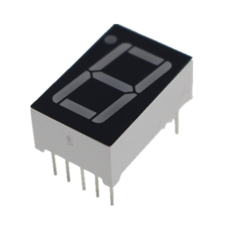
First and foremost, let’s delve into the anatomy of the 7-segment display. Each display consists of seven segments arranged in a figure-eight, accompanied by an optional dot segment, commonly referred to as the decimal point. The segments are named A through G, corresponding to their position:
- A: Top segment
- B: Upper right segment
- C: Lower right segment
- D: Bottom segment
- E: Lower left segment
- F: Upper left segment
- G: Middle segment
- DP: Decimal point (optional)
Your foray into controlling this display begins with understanding the electrical connections. Each segment must be connected to a microcontroller or any compatible digital device capable of outputting a low signal (typically ground) to illuminate the respective LED segment. A resistor is usually employed in series with each segment to limit the current and protect the LEDs from damage. The choice of resistor value is predicated on the voltage supply and the forward current specifications of the display.
Next, consider the wiring schematic: connect the common anode of the 7-segment display to your power supply, generally at a voltage of 5V for many components. Afterward, strategically connect the cathodes of each segment A through G (and optionally the DP) to the digital pins of your microcontroller. This setup paves the way for programming the microcontroller to manipulate the segment illumination.
The heart of controlling the display lies in programming. Whether you’re employing Arduino, Raspberry Pi, or any other microcontroller, the basic principle remains analogous. Initiate by establishing the digital pins as outputs in your code. Here’s a rudimentary example using Arduino syntax:
const int segmentA = 2;
const int segmentB = 3;
const int segmentC = 4;
const int segmentD = 5;
const int segmentE = 6;
const int segmentF = 7;
const int segmentG = 8;

void setup() {
    pinMode(segmentA, OUTPUT);
    pinMode(segmentB, OUTPUT);
    pinMode(segmentC, OUTPUT);
    pinMode(segmentD, OUTPUT);
    pinMode(segmentE, OUTPUT);
    pinMode(segmentF, OUTPUT);
    pinMode(segmentG, OUTPUT);
}

void loop() {
    displayDigit(5); // Call a function to display number 5
}

void displayDigit(int num) {
    // Logic to light up specific segments based on the number
    switch (num) {
        case 0: // Light up segments A, B, C, D, E, F
            digitalWrite(segmentA, LOW);
            digitalWrite(segmentB, LOW);
            digitalWrite(segmentC, LOW);
            digitalWrite(segmentD, LOW);
            digitalWrite(segmentE, LOW);
            digitalWrite(segmentF, LOW);
            digitalWrite(segmentG, HIGH);
            break;
        // Additional cases for other digits...
    }
}
This snippet orchestrates the display of numerical digits through clever segment activation, employing `LOW` signals to illuminate the segments, aligning with the common anode configuration.
Comprehending the display’s behavior extends beyond basic programming; it involves harnessing the myriad possibilities that this display offers. Innovations abound: envision augmenting your display with multiplexing techniques to showcase multiple digits. This strategy entails lighting segments in a rapid sequence, creating the illusion of simultaneous illumination. Though this demands precise timing and control, the resultant effect can be genuinely captivating and significantly expands the visual output potential.
Moreover, consider the robust integration of other components to enhance functionality. Temperature sensors, timers, or even communication modules can work in concert with your 7-segment display to yield real-time data on a compact, readable output. Whether you aim to visualize ambient temperature or relay countdowns during experiments, the possibilities abound!
To encapsulate your journey with a 7-segment common anode display, it’s paramount to acknowledge that each project fosters a learning experience. From mastering electrical connections to grasping programming concepts and exploring advanced techniques, every step enhances your prowess as an electronics enthusiast. So, can you rise to the challenge and unlock the full potential of this remarkable display?
Embrace the pursuit with zeal, and let your ingenuity dictate the directions you will explore. Each project awaits your touch, turning mundane digits into brilliant manifestations of your creativity and technical acumen.